Accessories
Optional imaging kit IMG-HR
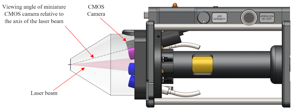
- 1/3-inch CMOS colour sensor 2.5 MP (1956 x 1266)
- Adjustable focus (approx. 20 mm to infinity – factory set during testing of LIBS system)
- Lens: f = 12 mm, f/1.8
- 12 VDC @
The video images are fed to the system computer via the USB frame grabber / capture device (Magewell) supplied with the imaging kit. There is one Magewell frame grabber / capture device for each camera being used. Note that these devices must be connected to USB 3 ports on the system computer using the proprietary USB cable (coloured blue) supplied with these devices.
Optional dual camera imaging kit IMG-HR-2
The optional dual-camera imaging kit IMG-HR-2 includes a second camera which is fitted inside the sample chamber (either SC-2XL or XYZ-750 only) as shown in the following diagrams. This camera provides a side view of the sample in the vicinity of the laser-induced plasma. The associated cable exits the sample chamber via a cable gland located in the rear panel of the sample chamber. This camera is equipped with an articulated mounting arm which allows the camera to be positioned manually at the desired position and then locked in place. In the diagram below, the camera and articulated mounting arm are highlighted in red. Note that the camera focus has been set during final testing of the LIBS equipment so it is necessary to position the camera at a distance from the object being viewed which results in a clearly focussed image. It may be necessary to adjust the position of the camera relative to the articulated arm mount by slackening the grub screw (see below) and sliding the camera towards or away from the object to help in this regard.
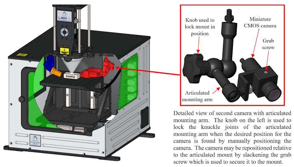
CAD view of XYZ-750 sample chamber showing second camera and articulated mounting arm (highlighted in red)
Gas-purge air pump
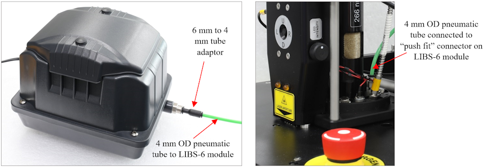
The LIBS-6 modules, LIBS-8 modules and LIBSCAN heads are equipped with a gas purge feature which allows air, nitrogen or preferably argon gas to be supplied via the acrylic nozzle aperture to the area of the sample where the laser beam is directed. Argon is often used as a purge gas with LIBS since it increases significantly the intensity of the recorded spectra, especially in the UV region (see Test Report for example spectra which show this). Although it is not necessary to use gas purge when conducting LIBS analysis of a material, it is recommended that at least air is used as a purge gas so as to help to keep the optics free of ejected material from the laser plasma. In view of this, we provide with most of our bench top LIBS instruments a simple 20 litres per minute (lpm) air pump of the type used for aquariums to bubble air through the water. This is illustrated below. The pneumatic tube (coloured green) is connected to the “push fit” connector located on the optics array of the LIBS-6 / LIBS-8 module as shown below in the image on the right. This air pump may be left switched on for the entire time the LIBS equipment is in use.
|
230 VAC diaphragm air pump with 4 mm
outside diameter (OD) pneumatic tube fitted
|
Image of LIBS-6 module showing pneumatic
tube connected to “push fit” connector
|
The above air pump is not required when other gases are used, such as nitrogen or argon. When using a gas other than air, alternative means of controlling the pressure and flow rate of the purge gas must be used such as a suitable regulator and flow meter (not supplied with the LIBS equipment). A flow rate of typically 5 to 10 lpm is usually sufficient. The gas pressure must be limited to not more than about 5 pounds per square inch (psi), although longer lengths of pneumatic hose may require higher pressure but never more than about 10 psi.
WARNING: To avoid an explosion risk, never use flammable gases as purge gas
Fibre-optic cables
| Product Code | Description | Qty required |
| FC-UV-SR-2m |
Single core UV-VIS fibre-optic cable.
2 metre length, SMA terminated both ends,
Solarisation Resistant (SR), 400 µm core diameter
|
1 |
| FC-UV-2m |
Single core UV-VIS fibre-optic cable.
2 metre length, SMA terminated both ends,
200 µm core diameter
|
5 or 7 |
The LIBS-6 / LIBS-8 module is optically connected to the SpectroModule-6 / SpectroModule-8 spectrometer using six or eight optical fibres. One of the optical fibres is marked “SR” (solarisation resistant) and this fibre should be used for the Deep UV (DUV) channel (i.e. SPEC-1 on the spectrometer front panel and the purple lens holder at the 1 o’clock position as viewed from the front of the LIBS-6 / LIBS-8 module). Proceeding in a clockwise manner, the remaining plasma light lens holders should be connected to the SPEC-2 – SPEC-8 channels on the spectrometer using the fibre-optic cables. It is important to connect the plasma light collection optic to the relevant spectrometer channel on SpectroModule-6 / SpectroModule-8 and so the collection optics in the LIBS-6 / LIBS-8 module are colour coded accordingly. This is described in the more detail here.
LIBS sample kit
 LIBS sample kit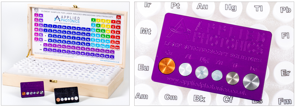
LIBS mugs!